MANHOLE CHAMBER
Product Description
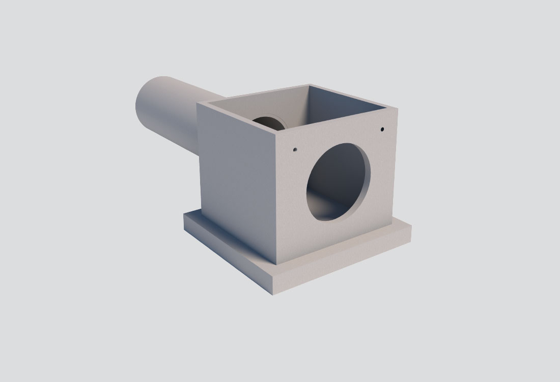
Manholes and Covers Precast manholes consist of three components: namely the base, the riser and the cone. The base, as the name suggests, is the bottom part of a precast manhole and is also where the sewage/water pipe is connected. The cone section is the topmost part of a precast manhole and is where access to the manhole is provided. The risers in a precast manhole are mainly there to help achieve the necessary depth from ground level. The wall thickness and grade/type of concrete used will vary based on the technical requirement of the client. Designs are dependent on project specifications and applications. Lateral earth loads from soil and hydrostatic loads from ground water. Vertical loads from the cover soil and live loads above. Surcharge loads from nearby impact loads. Seismic loads where applicable. After determining the size and design parameters required the appropriate ISO standards are used to provide the most economical design. Medium Duty: Designed for lateral earth pressure and hydrostatic loads from ground water, live load supercharge and adjacent vehicular traffic. Heavy Duty: Designed for lateral earth pressure and hydrostatic loads from ground water, live load supercharge and direct heavy vehicular loading. The internal diameter of a manhole can exceed 1500mm, however it cannot be manufactured using precast due to manufacturing and handling constraints. In the case of manhole diameters exceeding 1500mm, the base will have to be constructed using cast-in-situ above which a precast adaptor riser slab will be placed to reduce the diameter for the remainder of the manhole. Internal diameter: 600mm to 1500mm Cone height: 1200mm to 1400mm Standard base height: 1000mm Riser height: 200mm to 1500mm Grade: M30-M40 Manufacturing Method Manholes are cast using concrete with a low w/c ratio; it is poured into steel mechanized equipment called precast molds. Rebar is preplaced and secured inside the mould. Form vibrators are used to consolidate concrete to attain homogeneity and release any trapped air. Hole formers may be incorporated, or coring is done if needed. The product is then stripped and the mould is reused. At every stage meticulous testing is done to maintain quality. Every concrete batch undergoes cube testing to ensure strength parameters are met along with slump testing to ensure consistence in the mix design. After demoulding the product goes through visual inspection to ensure no honey-combing, voids or cracks are present. In case any test fails the batch will be rejected. 3. Installation Manholes are designed to be installed with ease, requiring very little excavation to place and a minimal amount of backfill. Manholes are supplied with lifting anchors along with male/female joints to make lifting and placing both easy and precise. Soil excavation followed by base preparation; levelled to ensure easy alignment. In the case where the water table is located in the trench zone, dewatering methods must be employed to remove the water. Backfill of soil should be granular and be compacted layer by layer beginning form the side walls to top of the manhole sections to attain the required minimum density. Male/Female joints are provided for each of the manhole sections to slide and lock into place. Furthermore erosion control seals, rubber rings, exterior joint wraps, expanding water stop seals or grouts can be used to make the joints watertight as required.

